Unknown Facts About Wedge Barriers
The 7-Second Trick For Wedge Barriers
Table of ContentsEverything about Wedge BarriersGet This Report about Wedge Barriers

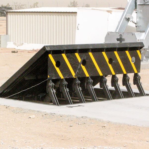
14 and the surface 12 to which the barrier 10 is protected may be made from concrete - Wedge Barriers. 2, the barrier 10 is mounted to or consists of an anchor or subframe (e. g., anchor 30 shown in FIG. 2 )secured underneath the surface 12. The bather 10 may be bolted to the support or safeguarded to the support by other mechanical fasteners. In the illustrated personification, the barrier 10 includes a wedge plate 16, that includes a section that is substantially identical with the surface area 12 when the barrier 10 is in the retracted setting. To put it simply, cars or people might overlook the barrier 10 when the barrier 10 remains in the pulled back placement and experience small elevation about the surface 12 while on the barrier 10. As gone over carefully below, when the obstacle 10 is in the deployed setting, the wedge plate 16 is held and supported in an elevated placement by a training system of the barrier 10. Additionally, the components 18 may be bolted or otherwise mechanically coupled to each other. In this way, repair service or substitute of several elements 18 might be simplified and structured. That is, repair or substitute of single parts
18 may be done quicker, quickly, and expense successfully. FIG. In specific embodiments, the support 30 may be a steel framework consisting of plates, beams(e. g., I-beams ), and/or various other structures that are secured within the foundation 14, which might be concrete. At the surface 12, a top side 28 of the anchor 30 may be at least partly revealed
, therefore allowing the add-on of the obstacle 10 to the anchor 30. g., threaded openings)in one or even more light beams or plates of the support 30 might be subjected to the surface area 12. In this manner, screws 32 or various other mechanical fasteners might be utilized to safeguard the obstacle 10 to the support 30. As the obstacle 10 is placed to the surface 12 of the foundation 14, collection of particles and other product underneath the barrier may be reduced, and elements of the bather 10 might not be revealed to listed below quality environments. As indicated by recommendation numeral 52, the lifting mechanism 50 consists of parts disposed underneath the wedge plate 16. For instance, the parts 52 beneath the wedge plate 16 might consist of an electromechanical actuator, a camera, one or more cam surfaces, etc. Additionally, the lifting device 50 consists of a spring setting up 54
The springtime rod 58 is paired to a web cam(e. g., web cam 80 shown in FIG. 4) of the lifting device 50. The springtimes 60 disposed concerning the spring rod 58 are held in compression by springtime sustains 62, including a dealt with spring assistance 64. That is, the fixed spring support 64 is taken care of about the foundation 14 et cetera of the bather 10.
The 6-Second Trick For Wedge Barriers
g., springtime support 65 )might be fixed to completion of the springtime rod 58 to enable compression of the springtimes 60. As the springs 60 are compressed in between the spring sustains 62, the spring assembly 54 generates a pressure acting upon the webcam combined to the more info here springtime pole 58 in an instructions 66. For instance, the continuing to be force put on
the web cam to deploy the wedge plate 16 might be provided by an electromechanical actuator 84 or other actuator. Because of this, the springtime assembly 54 and the actuator 84(e. g., electromechanical actuator)might run with each other to translate the web cam and raise the wedge plate 16.
As stated over, the spring setting up 54 applies a consistent force on the webcam, while the electromechanical actuator might be controlled to apply a variable force on the webcam, thereby making it possible for the training and lowering( i. e., releasing and retracting )of the wedge plate 16. In specific personifications, the continuous pressure used by the springtime assembly 54 may be adjustable. g., electromechanical actuator) is impaired. As will certainly be appreciated, the spring setting up 54 might be covered and safeguarded from particles or other elements by a cover plate(e. g., cover plate 68 received FIG. 4) that may be considerably flush with the elevated surface area 38 of the structure 14. As stated over, in the released setting, the wedge plate 16 serves to block access or travel beyond the barrier 10. For instance, the barrier 10(e. g., the wedge plate 16 )might block pedestrians or cars from accessing a residential or commercial property or path. As discussed above, the barrier 10 is affixed to the support 30 safeguarded within the structure 14,
front braces 71. As a result, the linkage settings up 72 may pivot and rotate to enable the collapse and extension of the Check This Out linkage settings up 72 throughout retraction and implementation of the bather 10. The link assemblies 72 reason activity of the wedge plate 16 to be restricted. If a lorry is traveling in the direction of the deployed wedge plate 16(e. For example, in one circumstance, the security legs 86 might be extended duringmaintenance of the barrier 10. When the safety and security legs 86 are deployed, the safety and security legs 86 support the weight of the wedge plate 16 against the surface area 12. As an outcome, the training device 50 might be deactivated, serviced, gotten rid of, replaced, etc. FIG. 5 is partial perspective view of an embodiment of the surface-mounted wedge-style obstacle 10, highlighting the camera 80 and the camera surfaces 82 of the lifting system 50. Particularly, 2 camera surfaces 82, which are described as lower camera surfaces 83, are placed below the cam 80. The reduced cam surfaces 83 might be dealt with to the surface 12 (e. For instance, the lower cam surfaces 83 and the mounting plate 85 might develop a solitary item that is protected to the anchor 30 by screws or other mechanical fasteners. Furthermore, two camera surface areas 82, which are referred to as top camera surfaces 87, are positioned over the webcam 80 and coupled to (e. In various other personifications, intervening layers or plates might be positioned in between the surface 12 and the lower cam surfaces 83 and/or the wedge plate 16 and the top webcam surfaces 87 As stated over, the cam
80 equates along the cam surface areas 82 when the wedge plate 16 is raised from the pulled back position to the released placement. Furthermore, as mentioned view it now over, the spring assembly 54 (see FIG. 3 )might provide a pressure acting on the cam 80 in the instructions 102 through springtime pole 58, which might lower the force the electromechanical actuator 84 is needed to relate to the webcam 80 in order to actuate and lift the wedge plate 16. 1 )to the deployed setting(see FIG. 4). As shown, the cam 80 consists of track wheels 104(e. g., rollers), which contact and translate along the webcam surface areas 82 during procedure.